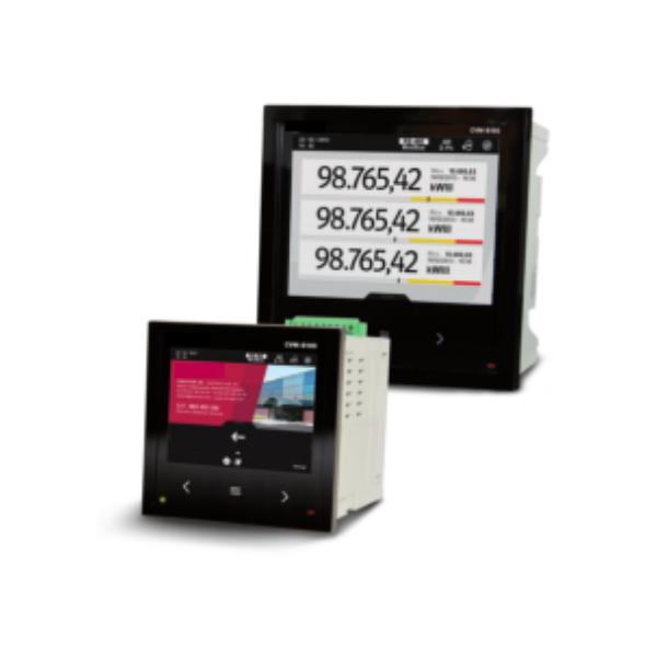

CVM-B Series
$0.00
Power Analyzers / Data Display
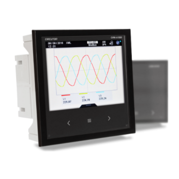
- High-resolution VGA colour screen
- Display: 3.77″ x 3.77″ or 5.66″ x 5.66″
- IP 65* front panel protection
- 5 voltage inputs (3 phases + neutral + earth) 1000V L-L
- 4 Current inputs, ITF
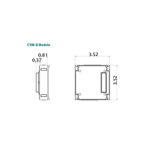
- Expandable unit, up to 4 modules, digital and analogue outputs
- RS485 communications port (Modbus/RTU and BACnet protocols)
- Voltage and Current harmonics to the 50th
- Innovative SCV interface for versatile data display
- 2 Relay outputs / 2 transistor outputs / 2 digital inputs
Product Description
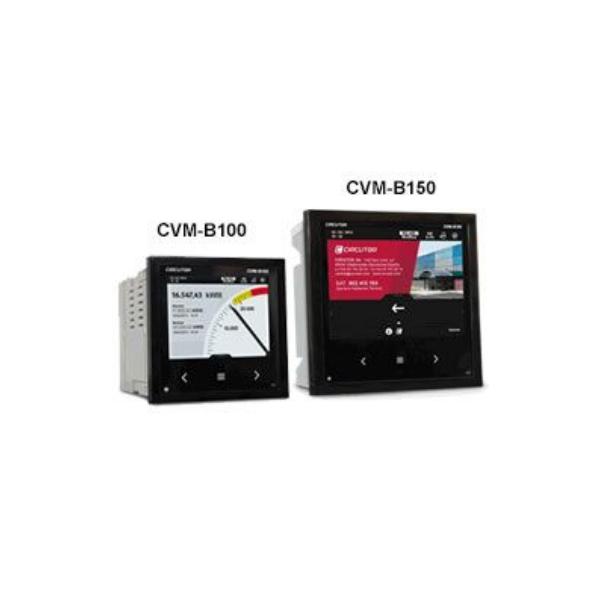
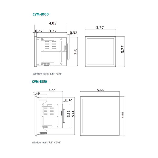
The CVM-B100 and CVM-B150 units are panel mounted three-phase power analyzers (dimensions: 3.77″ x 3.77″ and 5.66″ x 5.66″, respectively). Both offer 4-quadrant measurement (consumption and generation). Suitable for Medium or Low voltage installations, in both 3 or 4-wire three-phase circuits, two-phase circuits with or without neutral, single-phase circuits or ARON connections.
The CVM-B100 and CVM-B150 high-performance units feature a measurement engine that allows the user to analyse many different electrical parameters, in addition to offering a large variety of optional expansion modules for the same unit.
Features
- Format: 3.77″ x 3.77″ (CVM B100) and 5.66″ x 5.66″ (CVM B150)
- High-resolution VGA colour screen
- IP 65* front panel protection
- 5 voltage inputs (3 phases + neutral + earth) 1000 Vf-f
- 4 Current inputs, ITF
- Class 0.2 voltage and current accuracy
- Class 0.5S energy accuracy
- Voltage and Current harmonics to the 50th
- Expandable unit, up to 4 modules, combining digital and analogue outputs, Modbus/TCP, MBus, LonWorks, Profibus, XML/Web
- Modular (optional addition of expansion modules)
- Touch-sensitive movement buttons
- Universal power supply source
- RS485 communications port (Modbus/RTU and BACnet protocols)
- Customisation of parameters to be displayed
- Innovative SCV interface (Slide, Choose & View) for versatile data display, enabling the customisation of the parameters displayed on the screen
- Electrical parameters: instantaneous, maximum, minimum (with date and time) and demand
- Incremental electrical parameters (energy), times, costs, emissions
- 3 Tariffs (can be selected via the digital input or RS485 communications)
- Capable of showing costs and kgCO2 emission sources on the screen, depending on the energy consumed or generated
- 2 Relay outputs for alarms with delay, times, ON and OFF, etc.
- 2 transistor outputs for alarms or impulse generation, with all the possible configuration parameters
- 2 digital inputs, with control over the selection of the unit’s tariffs or configurable for monitoring purposes, with RS-485 Modbus communications, monitoring of logical states of other electromechanical units. (RCCBs, thermal-magnetic circuit breakers, etc.)
* with sealing joint
Applications
- Control and monitoring of all electrical parameters measured in any electric distribution panel and low and high-voltage connection points.
- 4 alarms (2 per transistor and 2 per relay), fully and independently programmable: low or high value, hysteresis, connection/disconnection delays, normally open or closed standby status and interlocking.
- Generation of impulses with transistor outputs, fully and independently configurable over any incremental parameter (energy, costs, kgCO2, total meter or tariff hours)
- Transducer that converts analogue signals to any instantaneous parameter that the unit can measure or calculate, with built-in expansion modules with analogue outputs.
- Display of process signals, with a built-in expansion module with analogue inputs; optional reporting of these signals to SCADA systems through communication systems
- Control of electrical load or alarm signal operations by programming the transistor or relay outputs that are built-in or added through expansion modules.
- Autonomous datalogger with web server, connected to a M-CVM- AB-Datalogger module. Enables direct monitoring of the historical data stored in the unit via a conventional web browser.
Specifications
| Power Circuit | CVM-B100 CVM-B150 |
| Voltage Measurement Circuit | CVM-B100 & CVM-B150 |
| Current Measurement Circuit | Current measurement 4 (3 phases + 1 neutral) |
| Maximum Transformation Ratios | Primary V : 6,000,000 (phase-neutral) |
| Maximum Meter Value (Total) | Yes (Primary A / Secondary A) < 1,000 (2 GW) |
| Accuracy Class | Voltage 0.2% |
| Voltage / Current | up to 50 |
| Digital Inputs | Selection of tariffs, states or external alarms |
| Digital Outputs | Generation of impulses or alarms |
| Alarms | Type Relay |
| Built-in Communications | Protocols Modbus RTU / BACnet |
| Environmental Conditions | Operating temperature -10…+50ºC |
| Format | Assembly on 3.7″ x 3.7″ or 5.6″ x 5.6″ panel |
| Safety | Designed for CAT III 300/520 Vac installations, in accordance with EN 61010 |
| Standards | IEC 62053-22, ANSI (class 0.5S), IEC 62053-23 ANSI C12.1 (class 2), IEC 61010, IEC 61000, UNE-EN 55022. Measurement in accordance with MID, design in accordance with UL IEC 61000-4-2, IEC 61000-4-3, IEC 61000-4-11, IEC 61000-4-4, IEC 61000-4-5 |
| References: 96x96 | Current measuring secondaries …/5 or …/1 A or …250 mA |
| References: 144x144 | Current measuring secondaries …/5 or …/1 A or …250 mA |