
Data Sheets & Downloads
Brochures
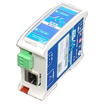
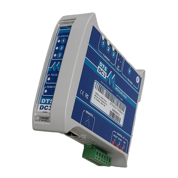
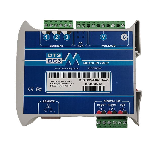
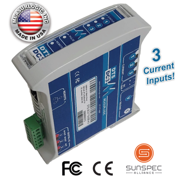
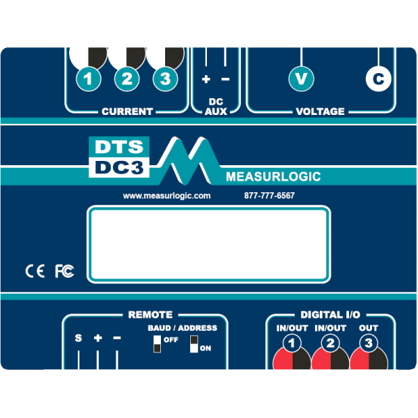
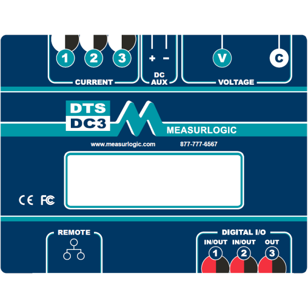
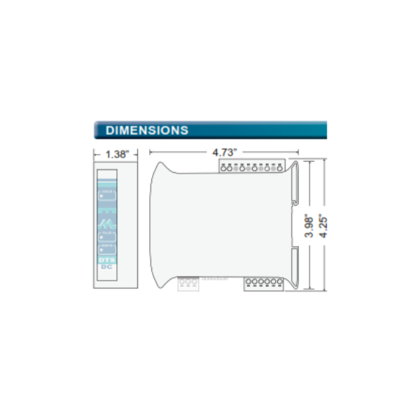
DTS DC3 Datasheet (2.2 Mb) [PDF]
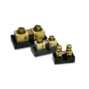
MLG-MK (DC Shunts) Series Datasheet (1 Mb) [PDF]
MLG-HE2 Hall effect sensor datasheet – (up to 200A) (255.7 Kb) [PDF]
MLG-HE4 Hall effect sensor datasheet – (from 500A up to 1000A) (256.5 Kb) [PDF]
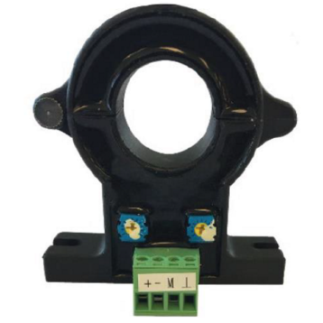
DC Hall Effect Datasheet (Solid Core – large aperture from 300A to 1200A) (790.6 Kb) [PDF]
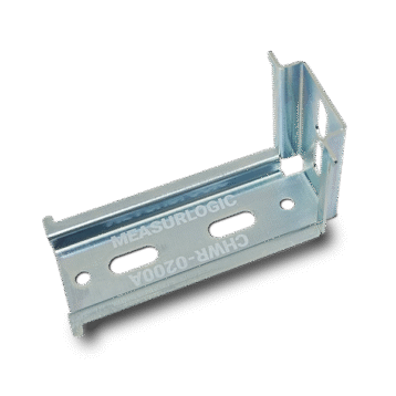
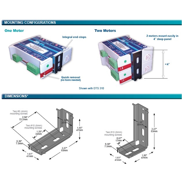
Right Angle DIN Rail Bracket Datasheet (1.4 Mb) [PDF]
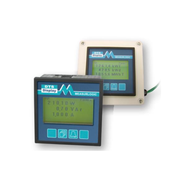
DTS Display Datasheet (1.2 Mb) [PDF]
Technical
DTS DC3-xx-SB-A-x Serial Modbus / BACnet Energy Meter Quick Start Guide (Up to 1000Vdc) (2 Mb) [PDF]
DTS DC3-xx-EB-A-x Ethernet Modbus / BACnet Energy Meter Quick Start Guide (Up to 1000Vdc) (337.9 Kb) [PDF]
Configuring AC and DC Current Sensors (308.7 Kb) [PDF]
DTS DC3 connection diagram RS-485 or Ethernet – 1 x shunt configuration (Up to 1000Vdc) (382.3 Kb) [PDF]
DTS DC3 connection diagram RS-485 or Ethernet – 3 x shunt configuration (Up to 1000Vdc) (177.2 Kb) [PDF]
DTS DC3 connection diagram RS-485 or Ethernet – 4-20mA HE2 or HE4 model hall effect sensors (Up to 1000Vdc) (393.7 Kb) [PDF]
DTS DC3 connection diagram RS-485 or Ethernet – 4-20mA HE2 or HE4 model hall effect sensors (1500 Vdc) (392.9 Kb) [PDF]
DTS DC3 connection diagram RS-485 or Ethernet – Positive Ground Topology (-48Vdc Telecom example) (444.6 Kb) [PDF]
DTS RS-485 Meter Setup using DTS Config & CCOM-0017 (1.7 Mb) [PDF]
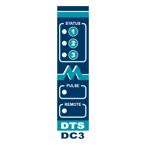
DTS DC3 – LED Definitions (261.4 Kb) [PDF]
RS-485 Cabling Requirements for Modbus RTU and BACnet MSTP (161.3 Kb) [PDF]
Configuring Digital IO using DTS Config (621.5 Kb) [PDF]
YouTube Videos
Accessing the embedded webpages – DTS Ethernet meters
Navigating the embedded webpages – DTS Ethernet meters
Using DTS Discover – DTS Ethernet meters
Connecting an Ethernet DTS meter directly to a laptop – Windows 11
Connecting an Ethernet DTS meter directly to a laptop – Windows 10
Software
Download DTS Config (Modbus ONLY)
Download DTS Discover (Preferred utility to detect DTS submeters with embedded ethernet port)
Download DTS Toolbox
Changing IP settings for an Ethernet based DTS meter (1.4 Mb) [PDF]
BACnet Explorers – 3rd party tools
View Software / Drivers page for more details & current version info.
Communications
DTS Modbus Map (732.5 Kb) [PDF]
DTS Modbus Addendum (SunSpec) (353.9 Kb) [PDF]
DTS BACnet MS/TP Map (539.8 Kb) [PDF]
DTS BACnet/IP Map (182.2 Kb) [PDF]
DTS LonWorks Map (274.7 Kb) [PDF]
DTS SNMP Map (146.1 Kb) [PDF]
— DTS AC Meters MIB File (2 Kb) [ZIP]
— DTS DC Meters MIB File (986 B) [ZIP]
DTS DNP 3.0 Map (157.1 Kb) [PDF]