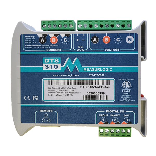
One of the most versatile and accurate meters on the market. The DTS 310 has a very compact DIN rail design, requires no external power source to operate, and comes with color coded, pluggable connectivity. This meter is certified to ANSI C12.20 Class 0.2 (Revenue Grade) providing the most accurate data acquisition available. It can function in either a single, split or three phase environment and is equipped with auto-topology detection. The DTS 310 works with all “safe” 333mV, 5A or flexible Rogowski current transformers (CTs) and comes with CT Reverse Algorithms for automatic correction of improper field mounted CTs.
For easy configuration in-the-field, communications can be set via DIP switches when utilizing the Modbus RTU or BACnet MS/TP protocols. Or for remote configurability, all the DTS Series of meters are offered with our DTS Config software platform; where you can conveniently choose from over 200 parameters. It also has a User-definable Modbus register area.
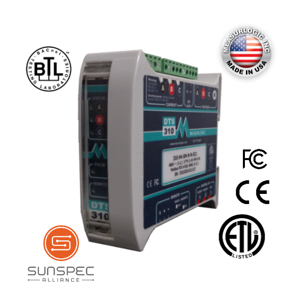
The DTS 310 is available with optional digital status/counter inputs or digital outputs, which can be used to import gas or water meters or to control any third party device; and is offered with optional on-board logging with our DTS Logging System. Also, if in the future, you decide to integrate renewable energy sources, the DTS 310 will conveniently operate as a Bi-directional NET meter. The DTS 310 is SunSpec Alliance certified and easily integrates with Building Automation Systems and Energy Monitoring Software. All our DTS Series of meters are designed and manufactured in the USA and comply with the Buy American Provisions of ARRA Section 1605.
Features
Line powered single / three phase energy submeter
Auto-topology detection
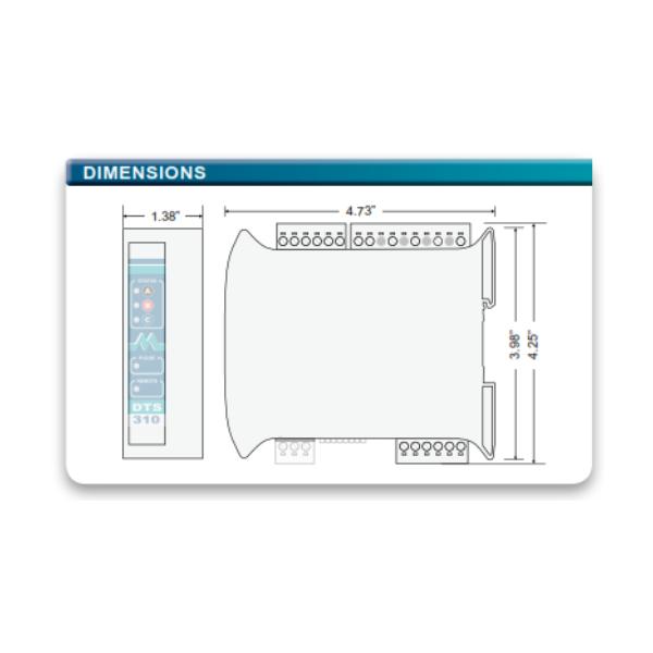
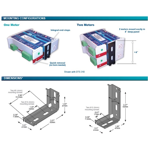
Compact DIN rail design: 4.73” L x 1.38” W x 4.25” H
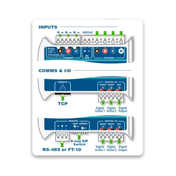
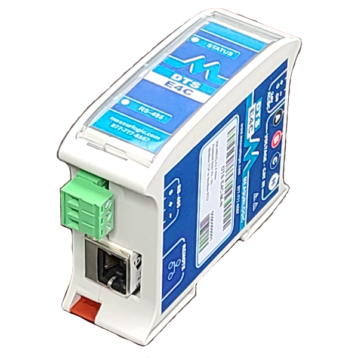
Ethernet connectivity – Modbus/TCP, and BACnet/IP by default, SNMP or DNP 3.0
RS-485 connectivity – Modbus RTU or BACnet MS/TP (field selectable)
DTS 310-P kWh pulse model ideal for VRF / VRV monitoring applications.
LonWorks FT-10 communications
Communications setting via DIP switches for Modbus RTU or BACnet MS/TP
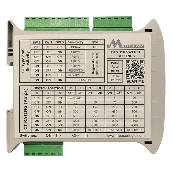
Interfaces with “safe” 333mV, 5A or Rogowski CTs
333mV models can be field selectable for 333mV or Rogowski CTs (NO integrator required)
User-definable Modbus register area
Bi-directional for renewable systems (NET metering)
Color coded, pluggable connectivity
Optional Low Voltage AC/DC Auxiliary (12-24Vdc or 24Vac)
Optional isolated 48Vdc Auxiliary
Optional single Pulse Output (kWh)
Optional 2 digital status/counter inputs OR digital outputs
User configurable using DTS Config software
Designed and Manufactured in the USA.
Complies with Buy American Provisions of ARRA Section 1605
Specifications
Measuring Circuits
Voltage range: 208-480Vac, L-L (CAT III)
120-277Vac L-N (CAT III)
Voltage overload: 1.1 x
Voltage burden: <0.1 VA @ 277 Vac L-N
Frequency: 45 to 65 Hz
Rated current: 333mV, 5A or model dependent
Current overload: 1.2 x
Power overload: 1.2 x
Accuracy
Voltage: 0.5%, <0.2% typical (80-120%)
Current: 0.5%, <0.2% typical (10-120%)
Power: 0.5%, <0.2% typical (10-120%)
Power Factor: 0.5% (between 0.5 and 1.0)
Energy:** Class 0.2 (ANSI C12.20)
Voltage Supply (Self Powered)
Voltage: Powered from Phase A & B or Phase A & Neutral (model dependent)
Frequency: 50/60 Hz
Burden: <2VA
Low Voltage Auxiliary (Option)
Voltage Options: 12-24Vdc or 24Vac
Tolerance: +/- 10%
Burden: <2VA
Isolation: Must be powered from a Class 2
IEC 60950 isolated power supply
Isolated DC Auxiliary (Option)
Voltage Options: 12 or 24 or 48 Vdc
Tolerance: -25%, +50%
Burden: <3VA
Isolation: 1500Vdc
Mechanical
Connection: Pluggable screw terminals suitable for 12AWG stranded wire (2.5mm2)
Case Material: Self-extinguishable, V0 plastic
Protection: Nema 1 (IP40)
Dimensions: 4.73”(120mm) D x 4.25”(108mm) H x 1.38”(35mm) W
Weight: 1lb (0.45 kg)
Environmental:
Operating temp: -4º to 158ºF (-20º to 70ºC)
Storage temp: -40º to 185ºF (-40º to 85ºC)
Humidity: 5 to 95% R.H. non-condensing
Communications (Serial)
Connection: 3 way pluggable, screw terminal
Protocols: Modbus RTU (SunSpec Certified) or BACnet MS/TP (BACnet Listed)
Communications (Ethernet)
Connection: RJ45, 10/100Base-T
Protocols: Modbus TCP (SunSpec Certified), BACnet/IP (BACnet Listed), SNMP or DNP 3.0 over IP
Communications (LonWorks)
Connection: 2 way pluggable, screw terminal
Protocols: LonWorks FT-10
Pulse / Status Outputs (Option)
Type: Potential Free, N.O. Solid State Relay
Pulse Width: Max 10 Pulses per Second
Pulse Rate: 1 Pulse / 1 KWh default, user configurable
Max On-Resistance: 30 ohm
Max switching voltage: 50Vdc or 30Vac
Max switching current: 120mA (350mA for 10mS)
Connection: Isolated Pin-Pair (Output 3, Outputs 1 and/or 2)
Status / Counter Inputs (Option)
Counter / Status Inputs: – Optional
Type: Dry Contact
Min Pulse Width: 50mS, Max 10 Pulses per Second
Max Current/Voltage: 15mA / 6V
Connection: 2 Pin-Pairs (Inputs 1 and/or 2)
Standards & Safety
ETL listing: 4001073
Conforms to: UL Std 61010.1
Certified to: CSA Std C22.2 # 61010.1
EMC:
IEC 61000-6-3 Emmissions, IEC 61000-6-2 Immunity,
IEC 61000-4-2, IEC 61000-4-3, IEC 61000-4-4,
IEC 61000-4-5, IEC 61000-4-6, IEC 61000-4-8,
IEC 61000-4-11
Emissions: CISPR 22 / FCC Part 15 Class A
Other: Measurement Category III – 300Vac L-N / 520Vac L-L
Communications: BTL Listed, SunSpec Alliance certified
RoHS: compliant